Collins Aerospace Pump Shutoff Senior Design Project
As part of my senior mechanical engineering capstone (ME 470) at the University of Illinois Urbana-Champaign, I worked with a multidisciplinary team to design an integrated shutoff valve for a modular aircraft fuel pump system sponsored by the Collins Aerospace engineering team, located in Rockford, IL.
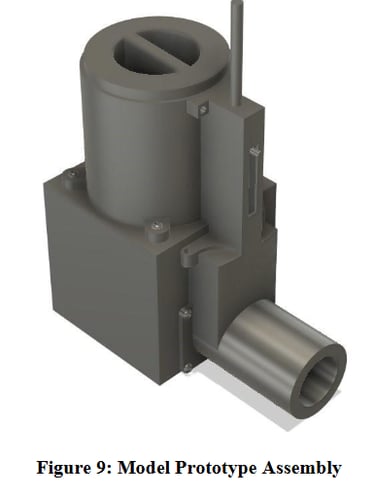
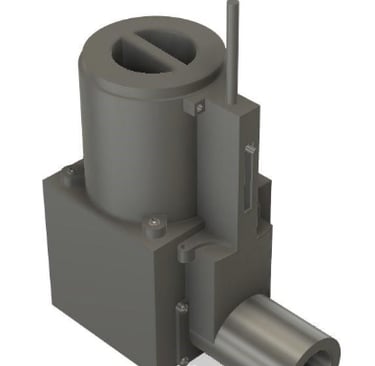
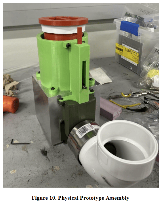
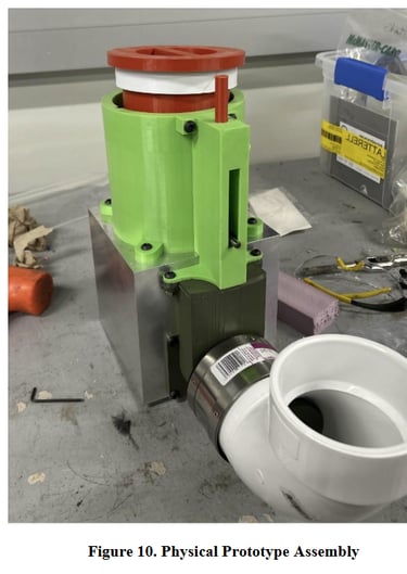
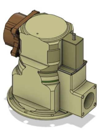
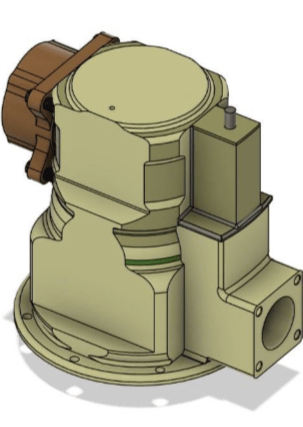
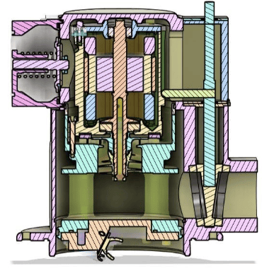
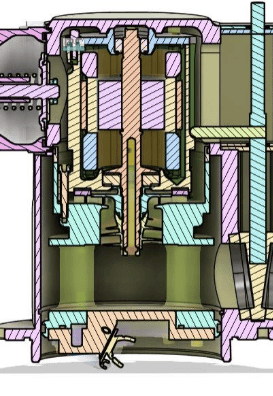
Background and Design Context: Aircraft fuel pumps must be periodically removed for maintenance, and existing designs can expose technicians to fuel leakage, safety hazards, and increased downtime. Our objective was to develop a low-cost, highly reliable internal shutoff mechanism that automatically isolates fuel flow during pump removal while meeting strict aerospace requirements, including less than 1 cc/min allowable leakage, 120 psi operating pressure, full jet fuel compatibility, and an effective service life exceeding 100 years. After evaluating multiple valve concepts, we selected a spring-actuated, self-sealing gate valve that interfaces directly with the pump’s locking mechanism, enabling passive shutoff without additional technician steps. I contributed extensively to mechanical design and validation using Autodesk Fusion 360 for CAD, Fusion Simulation for finite element analysis, and aPriori for manufacturing and cost modeling, supported by analytical calculations for hydrostatic pressure loading, spring preload, actuation forces, and material selection. The final design incorporated aerospace-grade materials including Aluminum 7075-T6 and Inconel alloys to balance strength, corrosion resistance, weight, and manufacturability. A functional proof-of-concept prototype was fabricated and tested to verify mechanism operation and sealing behavior. The Collins Aerospace engineering team expressed strong satisfaction with the final design, analyses, and documentation, validating its technical rigor and readiness for real-world aerospace maintenance applications.
ME 371 - Mechanical Design II: Remote Controlled Car
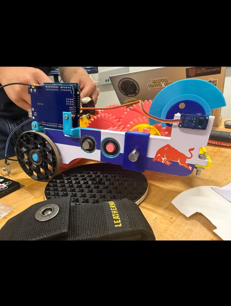
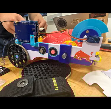
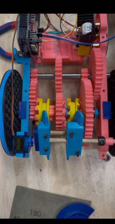
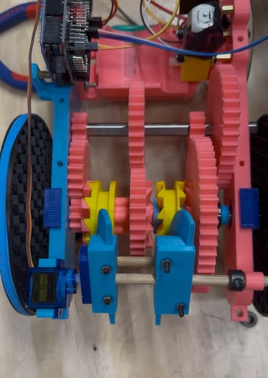
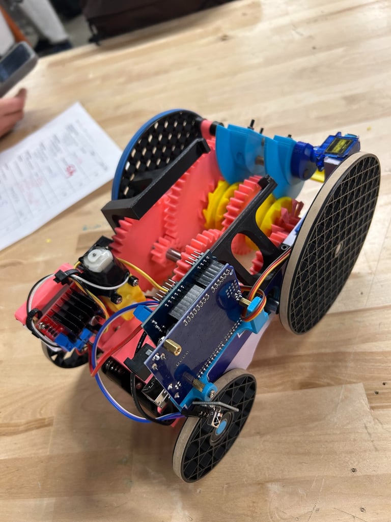
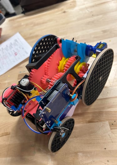
As part of ME 371: Mechanical Design II at the University of Illinois Urbana-Champaign, I worked with a four-person team to design and build a remote-controlled vehicle optimized for strength, efficiency, and mechanical simplicity as part of a semester-long mechanical design project. The final deliverable was evaluated in a multi-event heptathlon at the end of the semester, which scored vehicles on weight, cost, mechanical complexity, theme execution, speed, strength, and agility. Our vehicle featured a compact, fully mechanical three-mode drivetrain with high-speed, high-torque, and reverse gear selections, implemented using a dog clutch shifting mechanism actuated by a servo controlled through the provided remote transmitter. This allowed rapid, reliable gear changes under load while maintaining a lightweight and robust transmission architecture. Despite weighing only 700 grams, our car successfully carried 5 kg of payload in addition to its own weight, demonstrating an exceptional strength-to-weight ratio. In the strength event, the vehicle transported the payload up a 15° incline, earning first place by a large margin in that category. Across all heptathlon events, our team placed third overall in the class, highlighting effective drivetrain design, mechanical robustness, and system-level optimization under real-world competition constraints.
5 KG Weight Up Incline Ramp Video:

ME 370 - Mechanical Design I: Toy Automoton
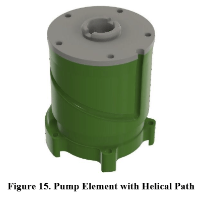
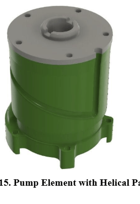
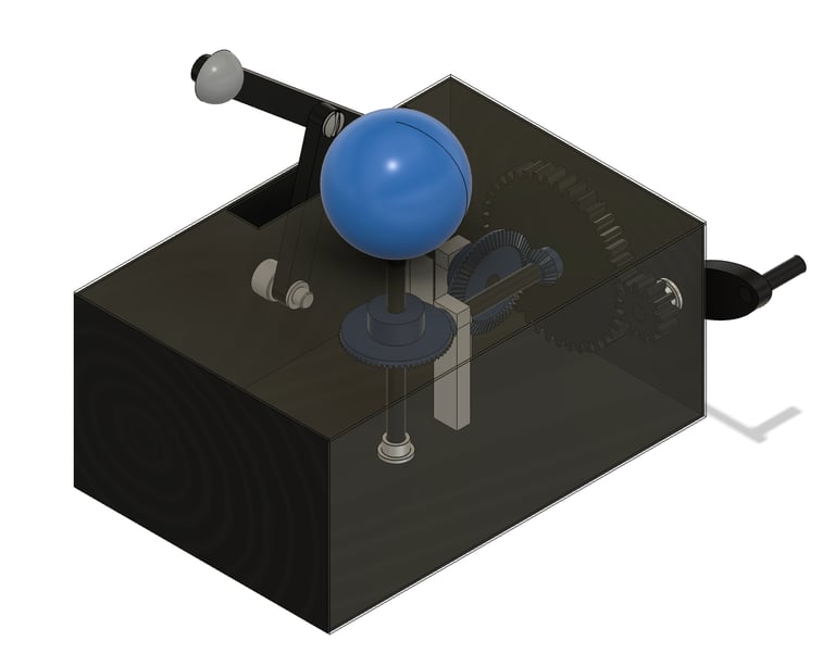
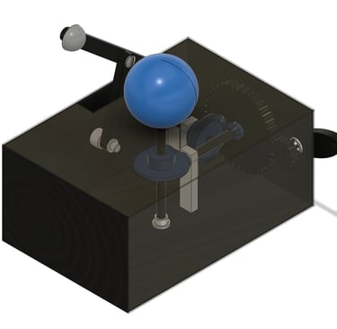
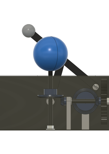
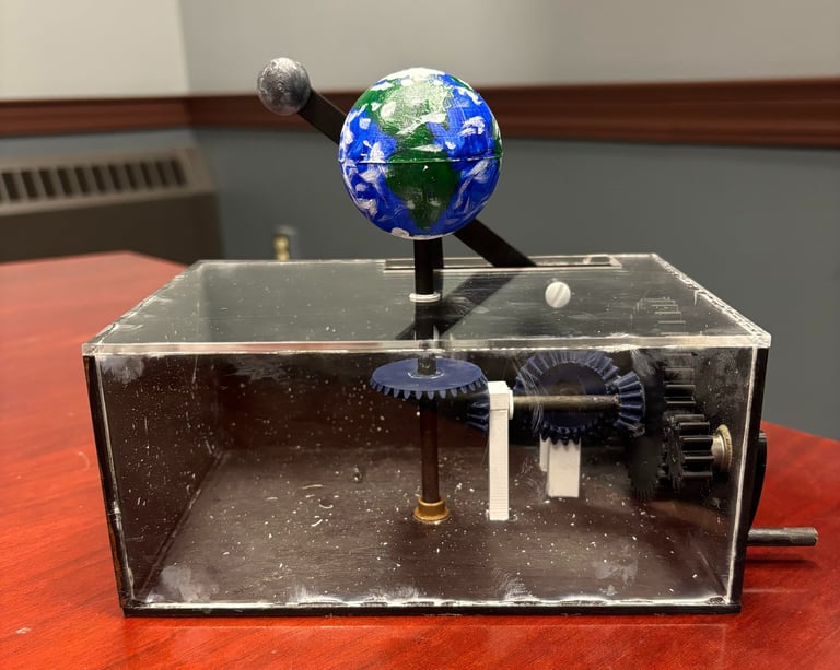
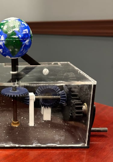
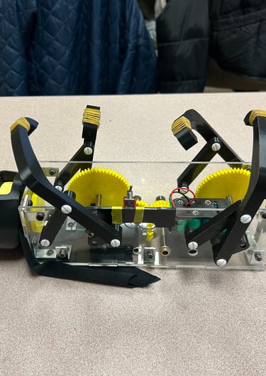
As part of ME 370: Mechanical Design I at the University of Illinois Urbana-Champaign, I worked with a four-person team to design and fabricate a themed mechanical toy automaton, with project requirements emphasizing creativity, mechanical clarity, and kinematic performance. A core constraint of the assignment was that the toy must feature at least two mechanisms moving simultaneously, driven by a single input, while remaining compact, robust, and visually engaging. Our team developed a planetary-inspired toy mechanism driven by a combined bevel and spur gear train, allowing rotational motion to be redirected and distributed to multiple outputs. As shown in the CAD views above, the gear train transfers input motion through orthogonal bevel gears into a spur gear system that drives simultaneous, coordinated movements within the toy, creating a dynamic and engaging visual effect consistent with our chosen theme. The design required careful consideration of gear ratios, shaft alignment, packaging constraints, and manufacturability to ensure smooth operation and repeatable motion. The final assembly successfully met all functional requirements and stood out for both mechanical execution and creativity, earning a top score relative to other teams in the class. This project strengthened my understanding of kinematics, gear train design, and translating creative concepts into mechanically sound systems.


ME 370 - Mechanical Design I: Robotic Rope Climber
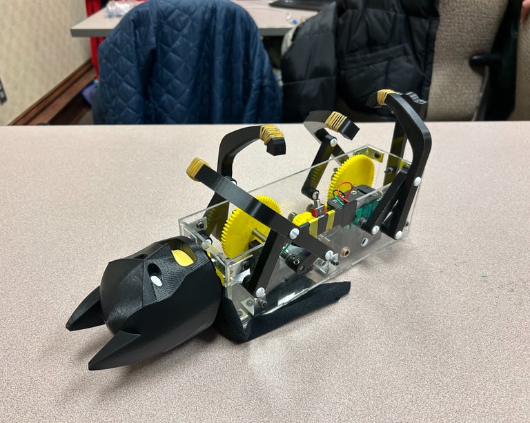
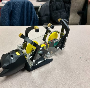
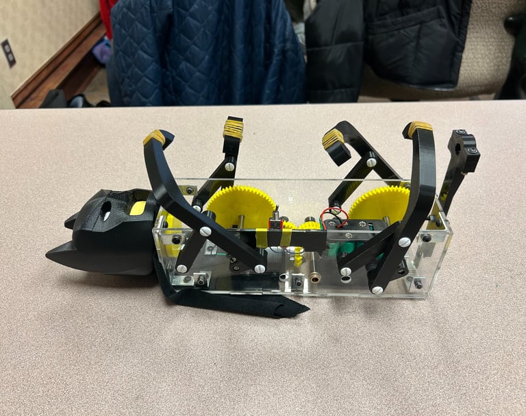
As part of ME 370: Mechanical Design I at the University of Illinois Urbana-Champaign, I worked with a four-person team to design and fabricate a themed mechanical toy automaton, with project requirements emphasizing creativity, mechanical clarity, and kinematic performance. A core constraint of the assignment was that the toy must feature at least two mechanisms moving simultaneously, driven by a single input, while remaining compact, robust, and visually engaging. Our team developed a planetary-inspired toy mechanism driven by a combined bevel and spur gear train, allowing rotational motion to be redirected and distributed to multiple outputs. As shown in the CAD views above, the gear train transfers input motion through orthogonal bevel gears into a spur gear system that drives simultaneous, coordinated movements within the toy, creating a dynamic and engaging visual effect consistent with our chosen theme. The design required careful consideration of gear ratios, shaft alignment, packaging constraints, and manufacturability to ensure smooth operation and repeatable motion. The final assembly successfully met all functional requirements and stood out for both mechanical execution and creativity, earning a top score relative to other teams in the class. This project strengthened my understanding of kinematics, gear train design, and translating creative concepts into mechanically sound systems.


Ergonomic Foundry Mold Storage Racks Project
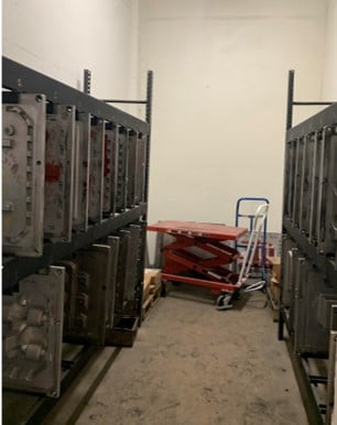
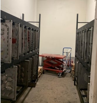
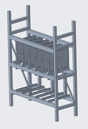
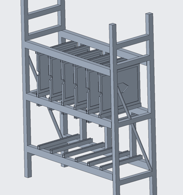
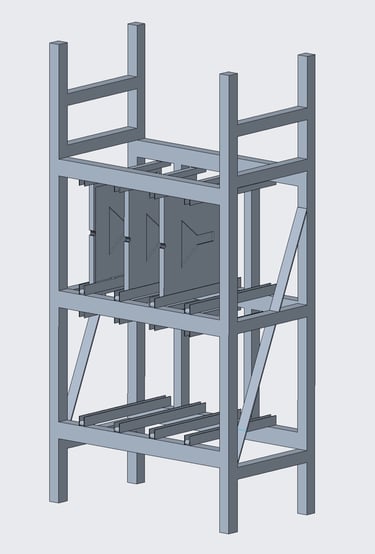
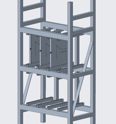
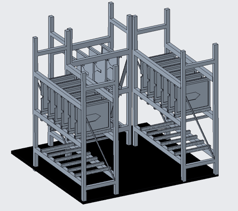
During my internship at G&W Electric Co., I was given two main projects to complete. The first is the stored molds racking project, which took place in G&W Electric's foundry (Manufacturer's Brass and Aluminum Foundry) in Blue Island, IL. This project focused on utilizing space in two "horse-stable" like rooms in the foundry by implementing new mold racks. I began this project by getting the dimensions of the room with a measuring tape, which is necessary for an engineering drawing to be made. After analyzing the rooms, I believed it would be most beneficial to implement two large racks (on each side) and one smaller rack (at the back of the room) for each room. Soon after, I began designing both racks in Creo using the dimensions I measured. Comparing my first design with my final, I achieved $4,000 in savings from using long, metal chains across the racks to prevent the molds from rolling out instead of individual toggle clamps for each mold. Soon after creating a Bill of Materials, ordering the parts, and the parts arriving, assembly began. Additionally, I included 1" rollers for ease of insertion/exertion as well as railing walls to prevent the molds from falling/swaying. Due to time constraints and delayed shipping of the parts, I did not have enough time left to finalize the project during my internship, however, it is currently being constructed and fabricated by my coworkers I worked with on this project.
Foundry Machine Operating Platform Project
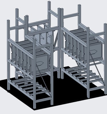
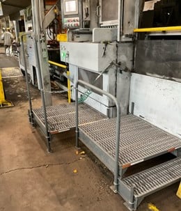
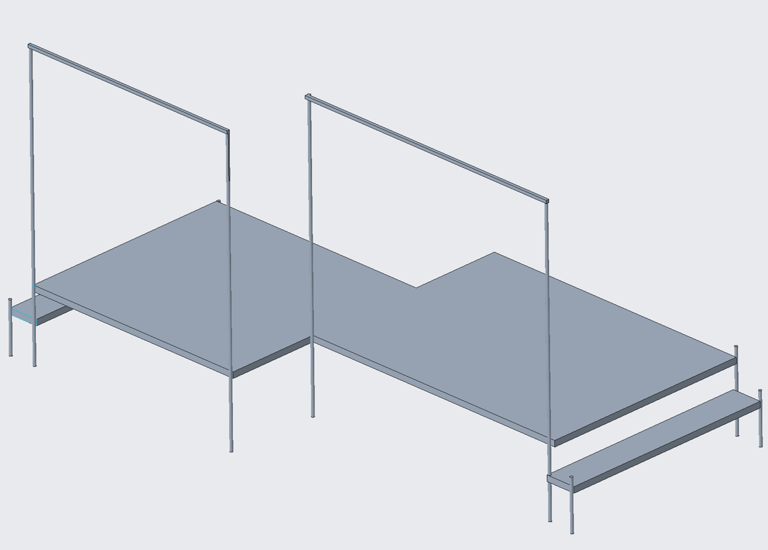
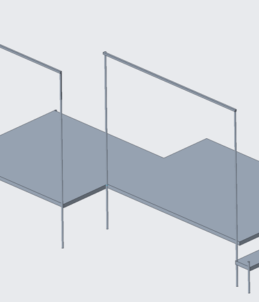
My second project during my internship at G&W Electric Co. focused on creating a more ergonomic operating platform for a $1.7 million molding machine (Sinto) in the company's foundry (MBAF). The operators have complained that they have been having difficulties accessing their cart since the current platform is not uniform and singular, which is essential to operate the machine. After measuring the dimensions of the working space and discussing with the operators, I began designing the platform using Creo. After designing the platform, I created a Bill of Materials, consulted with multiple steel vendors (achieved $1,000 in savings), and began assembly after receiving parts. Following the implementation of the platform, I revisited the foundry, and the operators were very happy with the result.
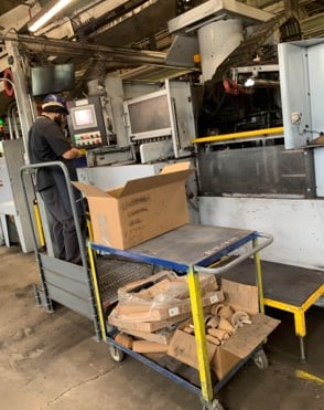
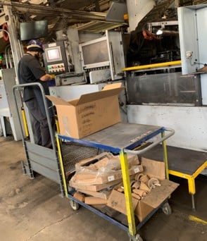
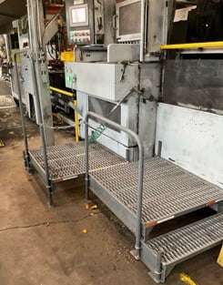
The top picture displays the Creo design I've created, and the bottom two pictures display the previous operating setup and the final implementation of the new platform, respectfully. As seen from the final implementation picture, the operator's cart is much more accessible, which will increase worker efficiency and production.
Plant Machinery Custom Laser-Cut Tags Project
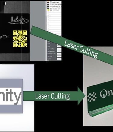
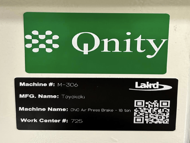
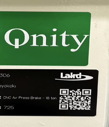
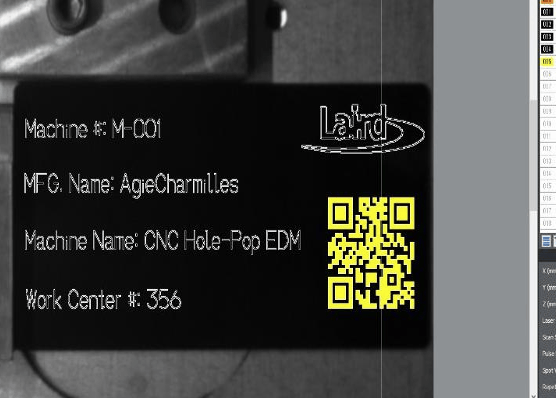
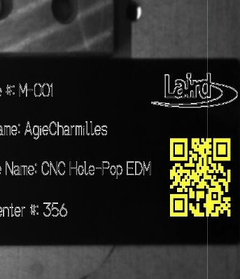
During my internship at DuPont (now Qnity Electronics), I led the design and implementation of a unified machine identification system to standardize equipment tracking across the manufacturing floor. The site had previously relied on multiple tracking systems and inconsistent work center tags, which caused confusion among operators and maintenance personnel, so the objective was to create a clear, scalable, and standardized solution. To achieve this, I designed custom laser-cut QR code equipment tags for all machinery and developed a reusable design outline and template in SolidWorks for the top “Qnity” logo tag. I also created a standardized layout in Marker Builder Plus, allowing each machine tag to be laser cut directly without redesigning individual tags from scratch. After fabrication, I securely installed the tags on each piece of equipment, ensured consistent placement throughout the plant, and verified their durability in a production environment. Each QR code links directly to MaintainX, enabling a fast scan-and-submit maintenance notification process. I additionally trained site personnel on using the new system, resulting in improved maintenance reporting efficiency, reduced operator confusion, and stronger communication across multiple production areas.

"Lapster" Project
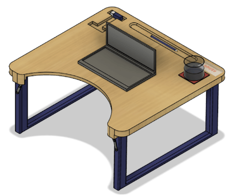
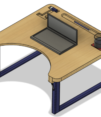
During my first semester in college, I worked with a team of three other students to design a portable lap desk in ME 170 – Computer-Aided Design, a project focused on creating a unique product tailored to the needs of everyday UIUC college students. Our team began by brainstorming user-centered ideas, developing hand sketches, and systematically evaluating concepts using a Pugh Matrix to compare criteria such as ergonomics, portability, stability, and manufacturability. After selecting a final concept, we used Autodesk Fusion 360 to create a detailed 3D model that emphasized ergonomic comfort, efficient use of space, and realistic mechanical constraints. The final design incorporated fully functional hinge mechanisms, including custom-designed joints and screw assemblies that allowed the lap desk to fold for portability while maintaining structural stability during use, resulting in a sophisticated and practical product that demonstrated a complete engineering design process from concept generation through detailed mechanical modeling.
Repurposed Kerosene Lantern Project
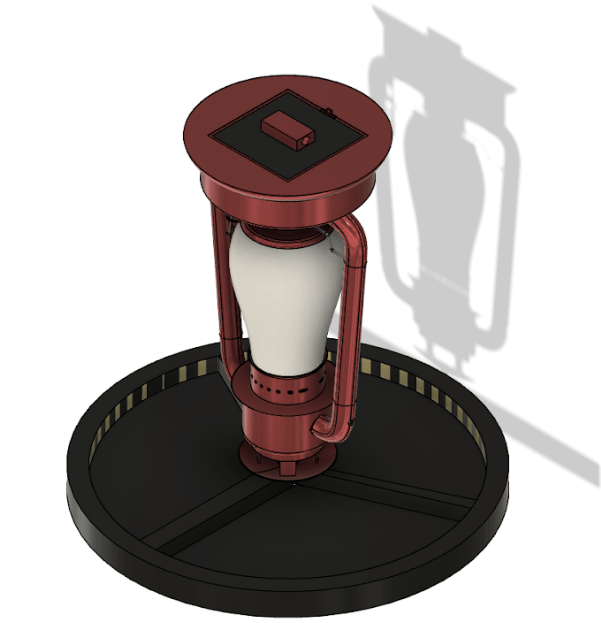
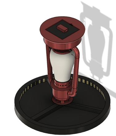
In ME 270 – Design for Manufacturability, which I took during my sophomore year, the individual final project challenged students to repurpose a dysfunctional household object into a product with a new and practical function. I selected an old kerosene lantern and engineered it into an innovative and visually appealing bird feeder, emphasizing both functionality and manufacturability. The design involved inverting the lantern and introducing bird feed through the bottom (functionally the top), allowing it to flow through the body and dispense onto a welded, evenly divided three-section feeding plate attached at the base to promote balanced feeding access. The project required thoughtful consideration of material selection, fabrication methods, and assembly processes, resulting in a robust and efficient design. The creativity and technical execution of the final product were well received, and I earned an A in the course.
The picture below displays my final computer-aided design of the repurposed lantern:
Wrench Design Project
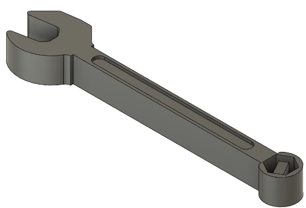
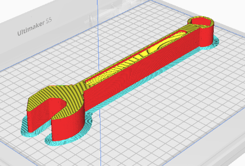
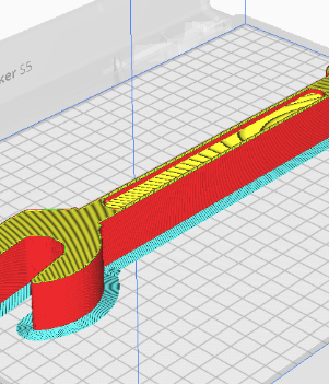
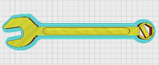
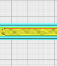
Another project I completed for the ME 270 - Design for Manufacturability course involved a CAD design and 3D printing analysis. For this project, I used Autodesk Fusion 360 to design an innovative object of my choice and then utilized UltiMaker Cura to evaluate and determine the optimal printing orientation, ensuring the best combination of strength, efficiency, and surface quality.
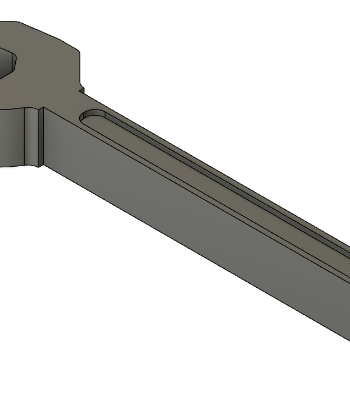
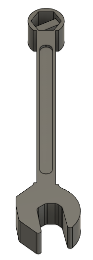
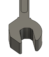
The pictures below display my final computer-aided design of the wrench:
3D Printed PLA Toy Car Project
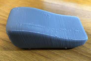
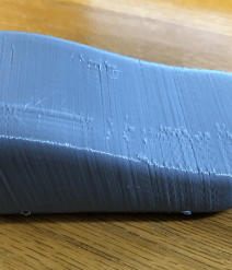
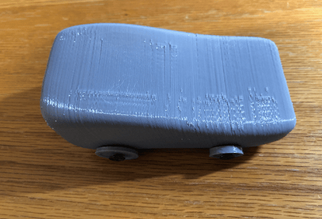
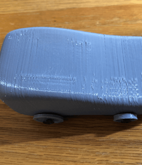
This project aimed at enhancing our 3D printing skills (FDM) using UltiMaker Cura. At the Jackson Innovation Studio in the Sydney Lu Mechanical Engineering Building, several high-tech 3D printers have been recently installed, which has allowed us to design and create more intricate objects. The way I intended to design the car (in Fusion 360) was to first create the body with a curved slope, then to add holes that cut all the way through for axles to fit with the wheels attached on each side.
The pictures below display the toy car without the axles/wheels and the final 3D printed toy car, respectively.
Side Project: Stick Welding
This past summer during my internship, I had the amazing opportunity to work in the fabrication apprenticeship program at G&W Electric Co. Every Tuesday and Thursday, I would participate with the apprentices and learn about metal fabrication, stick welding, brazing, and more. Scott Erickson also instructed me one-on-one at G&W Electric Co., a skilled welder who has worked at the company for many years and even teaches as a welding professor at Morton college. Steve Gilbert, another skilled professional at G&W Electric, was another teacher that taught the apprenticeship classes.
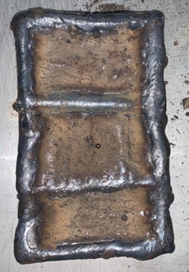
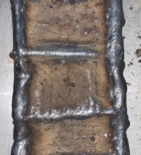
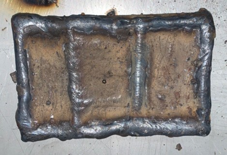
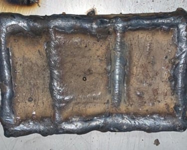
Apprenticeship Project 1: 3 Stairsteps
This project focused on developing our straight weld lines across a surface. As seen from the pictures to the right, each "level" is slightly higher than the previous. Additionally, we were instructed to alternate the weld direction for each step. For example, the weld lines for first step run from right to left, the second step up and down, and the third step back to right to left.
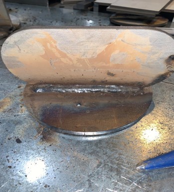
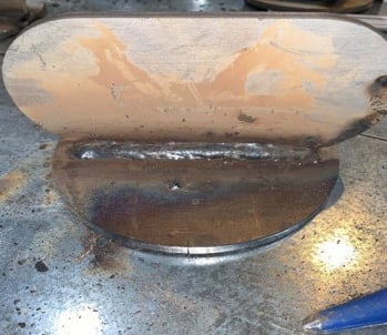
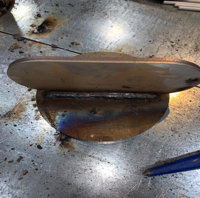
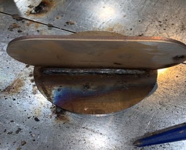
Apprenticeship Project 2: T-Joint
This project focused on perfecting a T-joint weld and ensuring the connecting piece is straight, even, and sturdy.
Welding Video on Sinto Platform (see project description above)